Release Date:2022-10-09 Views: 19
Treatment of terminal rectifier. At present, the efficiency improvement of server and communication system is mostly carried out at rectifier level. Rectifier efficiency of mainstream manufacturers is 90% to 96%. The rectification efficiency can reach 98%, but its application is still limited by the availability and cost of wide band gap devices and control circuits. In addition to efficiency, the power density of rectifier is also a key requirement in the design of data center. Higher rectifier power density will free more space for installing servers
The rectifier consists of a regulated power factor stage (PFC) and an isolated DC/DC converter. In order to achieve 98% rectification efficiency, PFC and DC/DC need to operate at 99% efficiency level. The traditional PFC with a peak efficiency of 97.5% is no longer suitable for this design. Bridgeless PFCs have become the only choice for the design of new generation rectifiers. At present, there are two different bridgeless PFCs topologies in the product, as shown below.

Dual Boost Bridgeless PFC& nbsp; & nbsp; & nbsp; & nbsp; & nbsp; & nbsp; & nbsp; & nbsp; & nbsp; & nbsp; & nbsp; & nbsp; & nbsp; & nbsp; & nbsp; & nbsp; & nbsp; & nbsp; ZVS CRM Staggered totem pole PFC
Dual boost power factor correction is essentially composed of two boost converters. One works in the positive cycle of communication and the other works in the negative cycle of communication. It reduces the number of semiconductor devices on the power processing path from traditional 3 to 2, thereby improving the efficiency. The advantage of this topology is simple control. The traditional PFC controller can be applied in this topology with a little adjustment. The disadvantage is that two boost inductors are required, which will increase the BOM cost and affect the improvement of power density. Due to the high current ripple of the step-up inductor and the difficulty in designing EMI filters, the power handling capacity of single-phase CRM (critical current mode) PFC is very limited (< 500W). ZVS CRM PFC topology with power over 500W usually adopts two-phase interleaving. By staggering the switching cycles of the two phases by 180 degrees, the current ripple can cancel each other, and the total ripple can be reduced to an acceptable range.
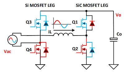
With the maturity of silicon carbide and gallium nitride and the reduction of cost, the rectifier design can adopt a more superior and simpler topology to achieve the overall efficiency of 96%+and work at a higher switching frequency. The following is the totem pole PFC of CCM (continuous current mode), which is very suitable for kilowatt level rectifier design.

CCM Totem pole PFC
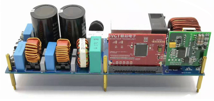
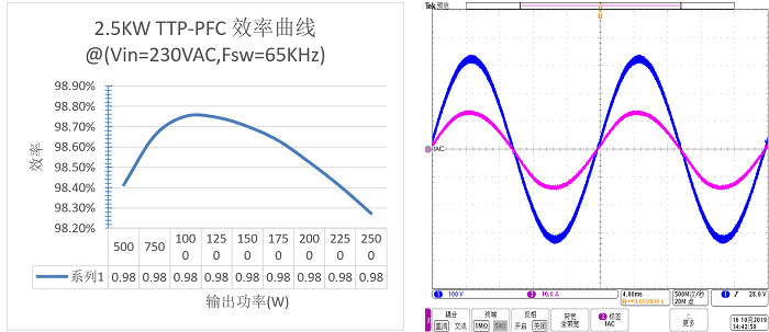
IVCT developed the reference design of 2.5kW totem pole PFC. The following are the reference design photos and key test data.(IVCT-REF00001)

2.5kW totem pole PFC reference design

Reference design efficiency of 2.5kW totem pole PFC& nbsp; & nbsp; & nbsp; & nbsp; & nbsp; & nbsp; & nbsp; & nbsp; & nbsp; & nbsp; & nbsp; & nbsp; & nbsp; & nbsp; Current and voltage waveforms of totem pole PFC
For DC/DC level, half bridge and full bridge LLC topologies are widely used. There are two main reasons for the transition of industrial medium from phase-shift full bridge topology to LLC topology. The main advantage of LLC topology is that it can realize full load range primary ZVS and wide load range secondary ZCS. The secondary side does not need inductance, 12V or 48V server/telecom output, and synchronous rectification circuit can be used to greatly reduce the conduction loss. These advantages make LLC more suitable for converter design with efficiency above 99%. Because the output current ripple of LLC converter is large, interleaved LLC structure is often used to reduce the output voltage ripple and reduce the self heating of output filter capacitor in the design of large current output.
Copyright © 2024 :Husheng Technology (Shenzhen) Co., Ltd
Support:wanet