Release Date:2022-10-09 Views: 28
Welding is a common method of joining metals, which is widely used. Welding power supply is a device that provides and regulates the current for arc welding. A low-cost and entry-level welding machine is the so-called "buzz box" welding machine, as shown in the figure below. It is a simple transformer containing saturable inductance or current control circuit. The two terminals of the transformer are connected with the base metal (workpiece) and the welding electrode. When the electrode strikes the base metal, the short circuit will cause a large current and cause an arc, which will melt the electrode and fill the gap of the base metal. Due to the limited control of this "electric welding machine", the welding quality depends on the operation level of the welder to a large extent. Heavy quality and high noise are other disadvantages of this welding machine. With the appearance of power semiconductor switch, advanced inverter welding machine was invented. High frequency switch technology and closed loop control are adopted to make the welding machine lighter and easier to use. The block diagram of low power inverter welding machine is shown below.

The welding gun and workpiece can be connected to the output of the welding machine in two different ways. When the welding gun is connected to the DC negative output, it is called "straight" welding (electrons flow out of the welding gun), otherwise it is called "reverse" welding. Among them, "reverse" welding is now used more. It is used for metal structures of bridges, ships and buildings, with good weld shape, deep penetration and good welding performance (bending, durability, porosity, etc.). Generally speaking, only DC "reverse" welding is used for welding on high strength and low alloy steel. Direct current "straight" welding is used for thin metal plates to prevent material burning through, or for metals that cannot tolerate sharp temperature changes or harmful moisture. The commonly used electric welding machine is constant DC output, but for aluminum welding, AC output (AC welding) at a certain frequency and mode is required. This is because aluminum parts basically have two layers, base aluminum and aluminum oxide. When metal aluminum is exposed to air, oxides will form. Its melting point is much higher than aluminum, about 3600 degrees Fahrenheit. For example, pure aluminum has a melting point of 1200 degrees Fahrenheit. Alumina must be removed before the base metal begins to melt. If this is not done, the base metal will not fuse well together; On welded sheets, the base metal may have overheated and liquefied before the arc penetrates the oxide. In these places, the cleaning efficiency of AC welding plays a role.
By controlling DC output polarity and duration, high quality welding effect can be obtained. The following is an example of waveform balance for aluminum welding in AC high-frequency TIG or AC up frequency TIG mode
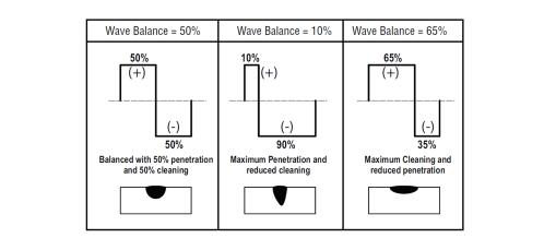
AC TIG wave balance
In order to output positive DC, negative DC and AC output, inverter welding machine needs to add a polarity switch circuit at the output end. The following is the circuit block diagram and current control outline diagram of general high-power welding machine.

Circuit Block Diagram of Universal Inverter Welding Power Supply Based on SiC Devices
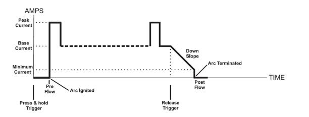
Current control outline diagram of inverter welding machine
Pulse power supply is a kind of equipment that can produce instantaneous high power at microsecond or nanosecond level. Pulse power supply is usually equipped with capacitor charger and pulse generating circuit with semiconductor switch and/or magnetic pulse compression (MPC) circuit system (saturated reactor). They can generate repetitive driving pulses with high accuracy and stability.
MPC circuit system uses magnetic switch, a saturated inductor, and takes advantage of the nonlinearity of the magnetization curve of ferromagnetic materials. A correct understanding of the saturation phenomenon, magnetic characteristics, volt second balance and switching characteristics of the magnetic switch is a necessary condition for the design of the magnetic pulse compressor. MPCs can output MW power at nanosecond level. They are widely used in water treatment, bacteria inactivation, high-energy particle beam, high-energy laser, strong x-ray source and other fields. With the commercialization of advanced SiC MOSFETs, a highly compact high power MPC design becomes possible. The following is an MPC power circuit based on SiC devices.

Power circuit diagram of 10s MW MPC based on SiC device
Generally, C1=N2 ∙ C2 and C2=C3. L1 and L2 are leakage inductances. The inductance ratio before and after saturation is 1:1000s - 10000s [1].
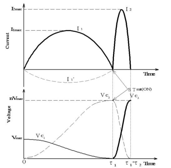
Ʈ 2 < 200 ns, I2max≈Several kA and Vc3max ≈ 20 kv - 140 kv, peak powerPmax≈10 MW。
The other is pulse power supply with semiconductor switch, which is usually used to generate microsecond pulse. There are two types of semiconductor based pulse power supplies. One is high voltage pulse power supply, the other is high current pulse power supply. A common use of high-voltage pulse power supply is air pollution treatment (household purification, flue gas produced by factories and automobile exhaust). The power circuit changes according to the power level (from 100s W for home application to MW for factory application), and the input PFC level is required by any system. The following is a resonant high-voltage generator circuit and typical output voltage waveform [2].

Circuit diagram of resonant high-voltage generator

Typical output voltage waveform
Taking the air treatment in the factory as an example, the high-voltage pulse generator applies DC voltage to the electrostatic precipitator and the positive pole is grounded, as shown in the figure below. When uncharged dust particles of polluted air pass through the chamber of electrostatic precipitator, they will be charged with negative charges first. These negatively charged particles are then adsorbed by positively charged dust collection plates. After all charged particles are adsorbed and "filtered", the air at the outlet becomes clean.
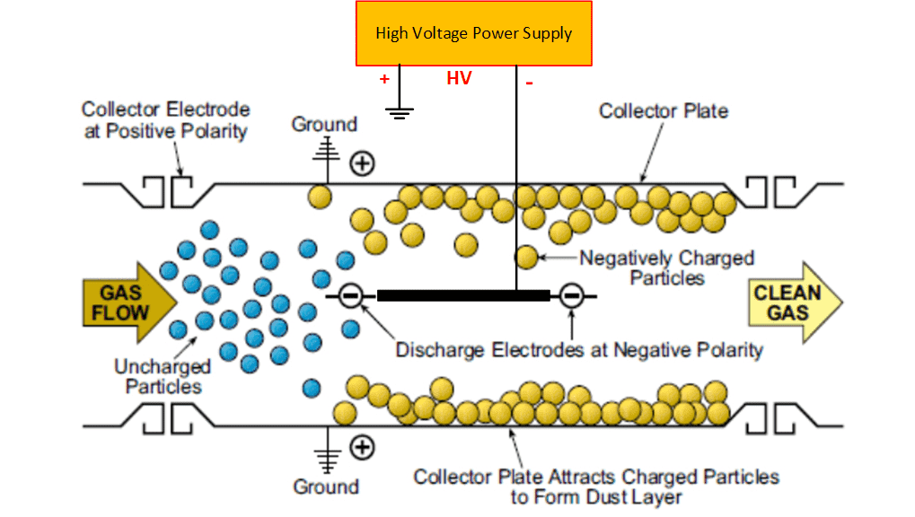
Principle of electrostatic precipitator
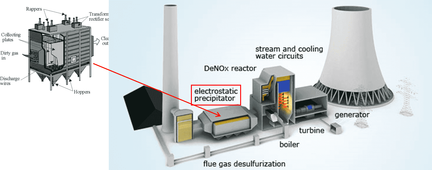
An air handling system for electrostatic precipitator in power plant
High current pulse power supplies are commonly used in laser applications. The following is an example of the product specifications of the QCW laser diode [3]。
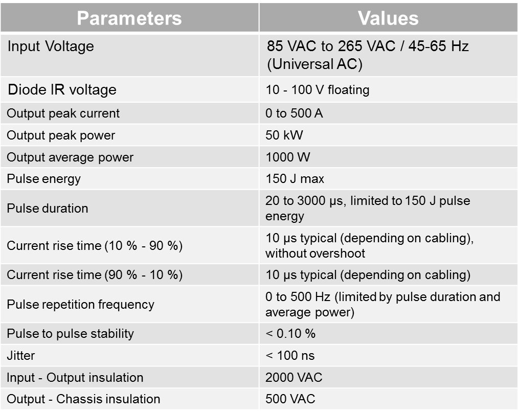
The pulse power supply can output 500A/100V or 50kW pulses, and the average input power is only 1kW. This pulse power supply is generally composed of three parts: isolated capacitor charger, capacitor bank and buck pulse generator, as shown in the figure below.

A typical laser pulse power supply circuit diagram
Circuit diagram of a typical laser pulse power supply

Other examples of high-voltage pulse power applications:

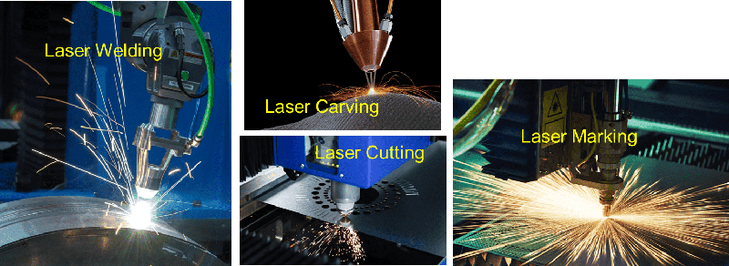
Application examples of high current pulse power supply:
[1] Jaegu Choi, “Introduction of the Magnetic Pulse Compressor (MPC) - Fundamental Review and Practical Application” .
[2] A. B. Jorgensen, S.D. Sonderskov, “Power Supply Prototype using SiC MOSFETs for Energization of Electrostatic Precipitators” .
[3] http://www.quantel-laser.com/en/products/item/id-500-a-100-v-pulsed-power-supply-.html
Induction heating is the best method to provide fast, accurate, clean, energy-saving, controllable and repeatable heating, which is applicable to the bonding of various metals or other conductive materials or the process manufacturing process to change their performance. Induction heating can quickly heat the workpiece while controlling contamination. This process depends on the heat generated by the induced current inside the material. Induction heating provides reliable solutions for cooking, brazing, quenching, preheating and post heating, shrink fitting, annealing, welding and other applications.
The power of induction heating can range from hundreds of watts to tens of kilowatts, depending on the size of the workpiece. The resonance frequency of medium frequency heating and high frequency heating is between 5-30kHz and 100-450kHz respectively. Medium frequency heating is usually used for large workpieces requiring deep penetration depth (such as diameter>50mm). High frequency heating is applicable to small size or thin parts.
For example, the induction cooker for home use only has several kilowatts and works at medium frequency.

At present, most solutions for induction furnaces use IGBTs. Due to the limitation of frequency and high conduction loss, the stove must use large coils and cooling fins with air cooling, which makes it difficult to seal the power board to prevent grease from entering the circuit board and the fan. The high-voltage SiC MOSFET can operate at a higher switching frequency and reduce the copper consumption of the coil, providing a simple solution for the design of new generation products. More importantly, due to the reduction of power consumption, fans can be eliminated, and the entire power board can be installed in a sealed aluminum box, which not only reduces costs, but also improves the reliability of electrical appliances.
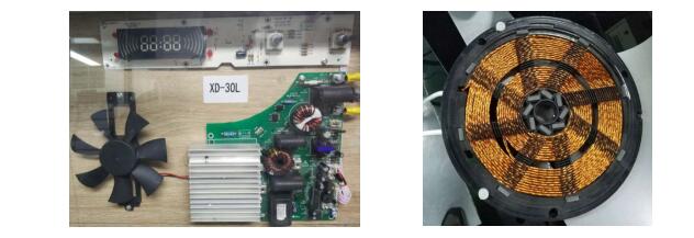
SiC MOSFET is designed to improve current IGBT based solutions
For tens of kilowatts of induction heating, PFC circuit is necessary. The following is a typical induction heating power circuit.
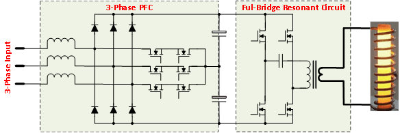
High power induction heating scheme
Silicon carbide electronic devices that can work under high temperature and large current can eliminate the need for special refrigeration and cooling of the system, which will revolutionize the induction heating system. SiC high power solid-state switch will also greatly improve the efficiency of power management and control. Silicon carbide electronic devices have been proven to work at extremely high temperatures, high frequencies and high power. The application of silicon carbide devices will make great progress in the field of high-frequency high-power induction heating.
The flexibility of the energy storage system provides a series of advantages for the efficient and reliable operation of large-scale power generation and transmission systems. The energy storage system improves the efficiency of power grid operation and reduces the line loss caused by local power congestion during the peak period of the power grid. The energy storage system can also reduce the need to build more power plants to meet the peak demand of the power system. With the increasing use of solar photovoltaic power generation and wind power generation, the combination of energy storage and renewable energy will likely change the way we produce, distribute and use energy in the next decade. This is greatly promoting the demand and large-scale development of integration of solar photovoltaic power plants and wind turbines with energy storage systems (ESS).
The battery energy storage system market is expected to achieve a compound annual growth rate of 33% from 2019 to 2024. Battery energy storage system has broad prospects in residential, non residential and public utilities. The main driving force of this market is the growing demand for grid connected solutions, the high demand for lithium ion technology in the renewable energy industry, and the falling price of lithium batteries.
The core component of ESS is bidirectional DC/DC and DC/AC power conversion system, which connects all power grids, photovoltaic panels, wind turbines, electric vehicles and batteries together and realizes power conversion between them.
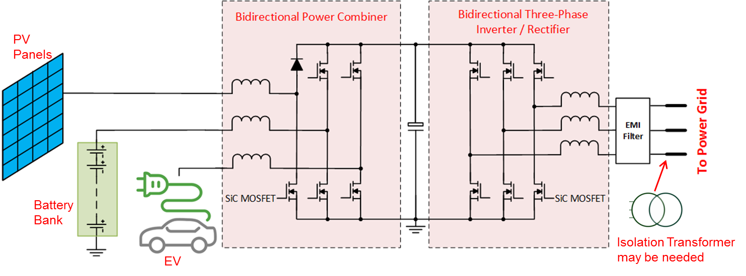
Renewable energy integrated battery energy storage all-in-one machine
For high-power battery ESS, in order to reduce copper loss, the bus voltage is usually set at 800V or higher; The choice of voltage depends on the power level of the system. SiC MOSFET has superior switching characteristics. At present, there is no competitive switching device in the field of hard switching applications requiring more than 20kHz switching frequency and 800V operating voltage. Silicon carbide diodes and MOSFETs are widely used in photovoltaic boost converters to improve power conversion efficiency and increase switching frequency. Because SiC MOSFET body diode has the characteristics of near zero reverse recovery, SiC MOSFET is an ideal switch for efficient bidirectional Buck Boost (half bridge) converter and bidirectional three-phase inverter/rectifier, which paves the way for system integration. The safe and reliable integration of photovoltaic panels, batteries and power electronics in a compact single module is an effective way to meet the rapid growth of scattered solar power stations and grid connection. This integration not only eliminates the need to customize each system, but also expands its application scope in power grid direct connection system and off grid system or portable equipment.
One of the application fields of off grid energy storage system is portable power supply with or without solar photovoltaic panels. Applications range from thousands of watts of campers to hundreds of kilowatts of emergency power supply for disaster relief. Battery pack and bidirectional AC/DC converter are two key components of portable energy storage system. The battery cost plays a leading role in the system BOM, and the efficiency of the converter directly affects the kilowatt hour output of ESS. The new generation semiconductor switch SiC MOSFET replaces IGBT, which can improve the system efficiency by more than 2% (up to 99.3%), which gives SiC MOSFET a great opportunity to be widely used in this field. The following is a diagram of a battery portable power system and a 60kW silicon carbide three-phase bidirectional AC/DC (inverter/PFC) converter。
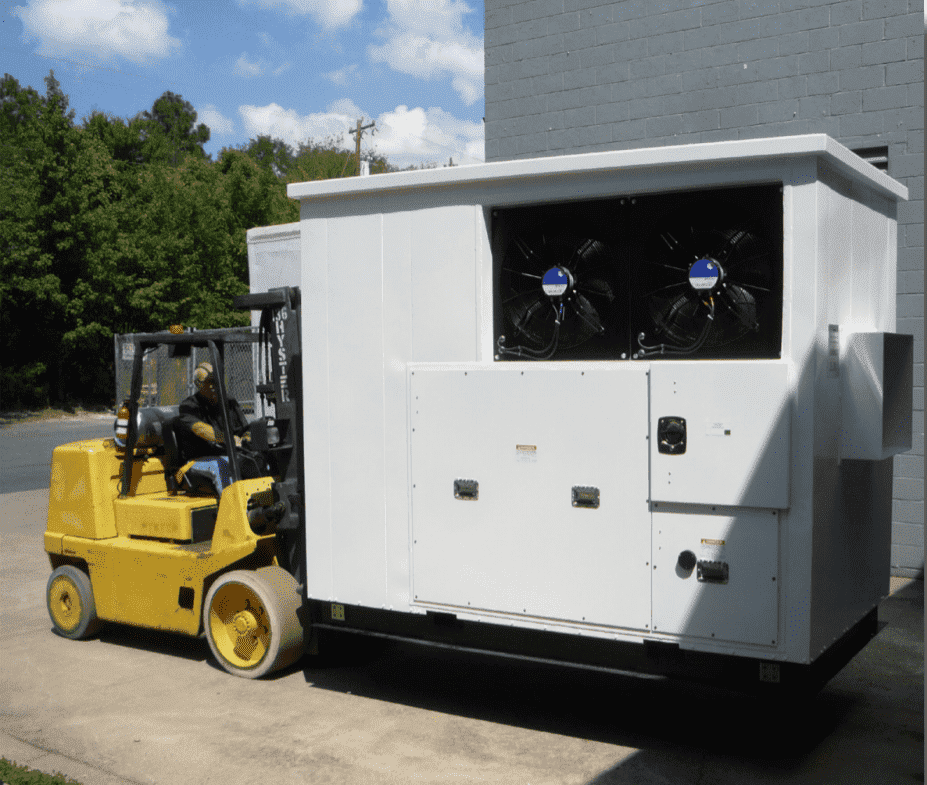
Portable battery energy storage power supply system
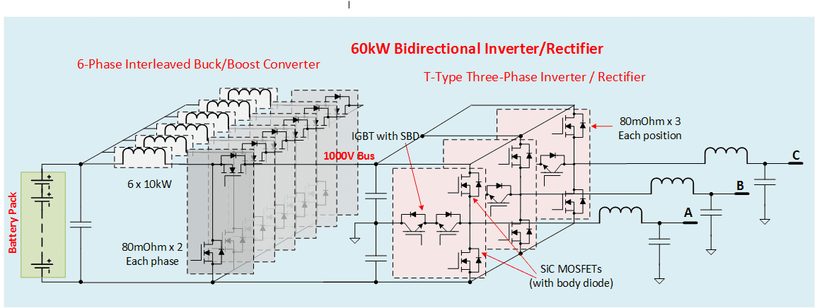
Diagram of 60kW three-phase bidirectional AC/DC (inverter/PFC) converter based on SiC devices
SiC technology can realize solutions of high voltage, high frequency and high efficiency, which is the key requirement of all energy storage systems. With the further decrease of battery price and SiC material cost, the energy storage system based on SiC devices will play a greater role in optimizing power distribution, stabilizing power grid, smoothing power demand, and making better use of renewable energy.
[1] "Battery Energy Storage System Market Report: Trends, Forecast and Competitive Analysis" , Research And Markets, Aug. 5, 2020
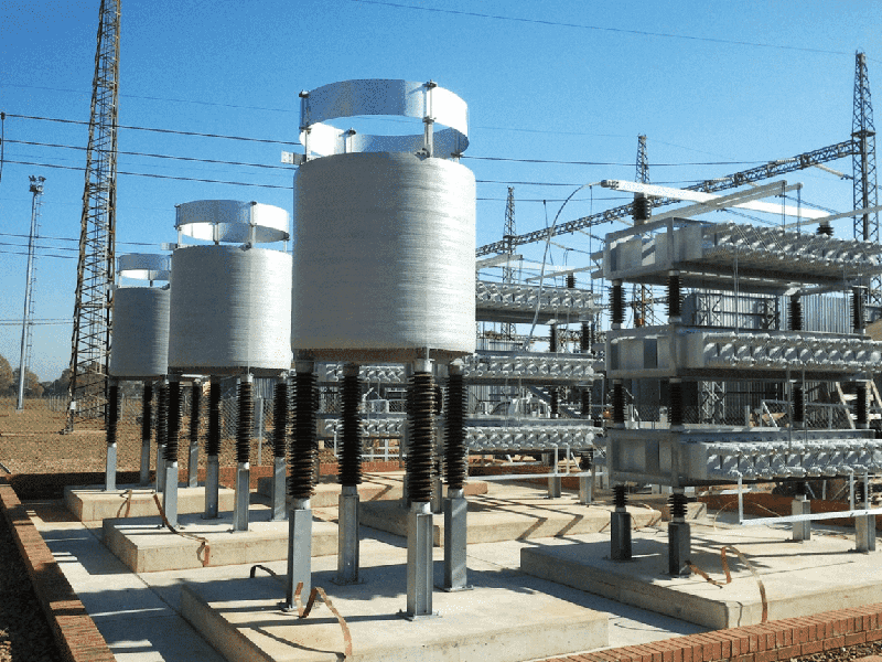
The traditional solution is to add passive filter and reactive power compensator in power system. The volume of integral filter and compensator accounts for a large proportion of the substation area, as shown in the figure below. Compensators can only be added or removed in stages, which has slow response and will cause certain disturbance to the power system itself.
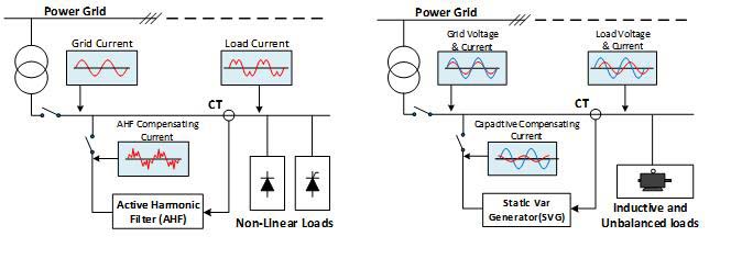
Active harmonic current compensation Active reactive compensation
With the development of power semiconductor technology and digital control technology, power line current can be monitored in real time, and reactive power and harmonic current can achieve optimal real-time compensation. Reactive power compensator, so-called static var generator (SVG) and active harmonic filter (AHF) are all inverter based systems. SVG injects power frequency current with required amplitude into the power network. In order to output high reactive power, SVG is usually connected to the grid and directly connected to the power line, as shown in the following figure:
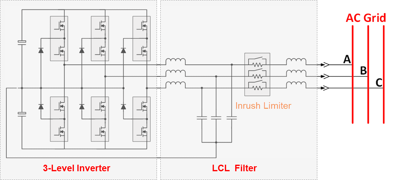
Grid connected circuit of three-level static var generator
AHF is essentially an inverter, which can inject reverse current to offset unwanted harmonics. Compared with SVG, AHF outputs relatively small current, but high harmonic order. In order to "filter" 40 order harmonics, AHF inverter needs higher switching frequency. For the 50Hz power frequency, the 40th harmonic is 2kHz, which generally requires the PWM frequency to exceed 40kHz to effectively level the 2kHz harmonic current component. SiC MOSFET is currently the only effective choice for (hard switching) applications where the switching frequency exceeds 20kHz,. The AHF can be connected in parallel or in series with the grid line.
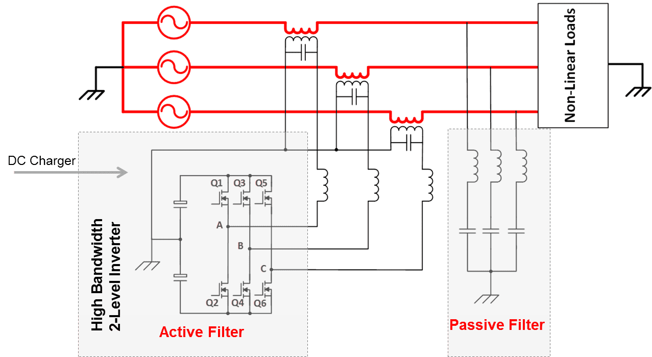
A two-level active harmonic current filter circuit connected in series to grid
It can be seen from the above block diagram that SVG and AHF both collect the load line current, and then use the inverter to generate the required current to compensate reactive and harmonic currents. In order to make full use of the equipment hardware and reduce the system cost, SVG and AHF can be designed together. The equipment with SVG and AHF functions is called power quality compensator (PQC).
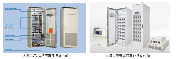
[1] P. M. Balasubramaniam , S. U. Prabha “Power Quality Issues, Solutions and Standards: A Technology Review,” Journal of Applied Science and Engineering, Vol. 18, No. 4, pp. 371380 (2015)
Variable frequency drive (VFD) has been widely used in industry and automobile. The key technology is to realize high frequency pulse width modulation (PWM) using semiconductor switches. Mainly, the two-level inverter operating in the switching frequency range of 4 to 16 khz generates three-phase sinusoidal fundamental voltage or current to drive the motor. For bus voltage of 400V and above, IGBT is dominant. With the emergence of wide band gap SiC MOSFET, its superior switching performance has rapidly attracted the attention of motor drive development. SiC MOSFET can reduce the switching loss by about 70%, or achieve the same efficiency at nearly 3 times the switching frequency. SiC MOSFET is more like a resistor without the PN junction voltage drop of IGBTs, which reduces the conduction loss, especially under light load. With the realization of higher PWM frequency and higher basic frequency of motor drive, the motor can be designed into more poles to reduce the size of the motor. Under the same output power, the volume of 8-pole motor can be reduced by 40% compared with 2-pole motor. High switching frequency makes high-density motor design possible. These performances show the great potential of SiC MOSFET in high-speed, efficient and high-density motor drive. The successful application of SiC MOSFET on Tesla Model 3 marks the beginning of the era of SiC based motor drive. There is no doubt that SiC MOSFET will dominate the trend of automotive traction applications, especially in 800V battery vehicles and high-end industrial applications.
In order to make full use of the advantages of SiC MOSFET, the switching speed (dv/dt) and switching frequency should be one order of magnitude or more higher than the current IGBT based solutions. Although SiC MOSFET has great potential, its application is still limited by the existing motor technology and drive system structure. Most motors have high winding inductance and large parasitic capacitance. The LC circuit is basically formed by connecting the motor and inverter with three-phase cables, as shown in the figure below. The high dv/dt voltage at the output end of the inverter can excite the LC circuit oscillation, while the voltage spike at the end of the motor can reach twice the output voltage of the inverter. This will increase a lot of voltage stress on the motor winding.

When the inverter is directly connected to the motor, the cable voltage oscillation no longer exists. However, as shown in the figure, high dv/dt voltage changes will be directly applied to the winding, resulting in accelerated winding aging. In addition, high dv/dt voltage will induce bearing current, leading to bearing corrosion and early failure.
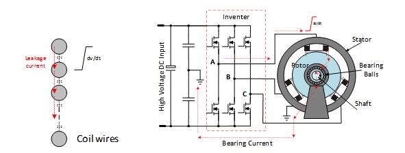
Winding turn to turn high dv/dt bias voltage High dv/dt will induce bearing current
Another potential problem is EMI. High dv/dt and high di/dt will induce higher electromagnetic interference radiation. The design of all IGBT and SiC solutions needs to consider these impacts.
To alleviate these problems, different technologies have been developed. If the motor and inverter driver must be separated, dv/dt edge filter or sine filter is an effective solution, but it will increase some costs. Since the IGBT inverter came into the market, the motor design has been improved. By using better insulated enamelled wire, improving the motor coil winding structure and shielding method, the motor's anti dv/dt capability has been greatly improved from the initial several V/ns, and will eventually reach the goal of 40-50 V/ns. The efficiency of inverter based on SiC devices is very high. The efficiency usually reaches 98.5% at 40kHz and 99% at 20kHz. Due to the low drive loss, integrated motor drives become a viable and attractive system solution, eliminating all cables and terminal connections, and reducing system volume and cost. Fully enclosed inverter driven motor is an effective way to reduce electromagnetic interference. The bearing current can be bypassed by short circuiting the motor shaft and stator through the grounding spring or brush. Compact, efficient, light weight, integrated motor drive is widely used in industrial robots, airborne, underwater UAVs and other fields.
In addition to the reduction of drive system size, SiC MOSFET also makes high-speed drive possible. High speed drives have gained more and more attention in automotive, aerospace, stirring, pump and compressor applications. High speed drives have become the latest technology in some of the above applications. In some niche applications, the use of high-speed drives has improved the performance, quality and innovation of products.
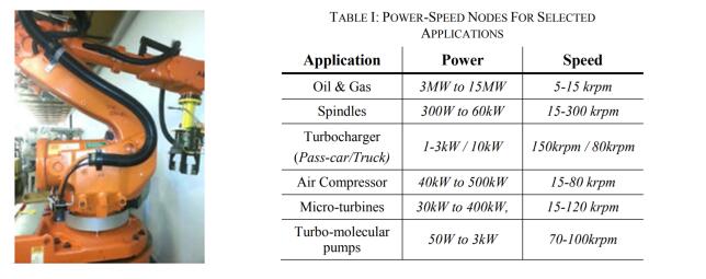
Integrated driven applications
In order to provide smooth sine wave drive, VFD switching frequency needs to be at least 50 times higher than AC current frequency. The switch frequency, pole pair and motor speed are closed系:
f_PWM = 50∙ Pole-Pair ∙ rpm /60
That is, for ordinary four pole motor, to reach 10 krpm, f_ PWM needs to be 16.6kHz, which is about the limit switching frequency of IGBT. Therefore, SiC MOSFET becomes the first or only effective choice for any motor speed exceeding 10 krpm. In order to improve the motor power density, it is usually necessary to increase the number of poles, which requires higher PWM switching frequency. The use of silicon carbide will promote a new round of improvement and innovation in motor design.
[1] R. Abebe, M D. Nardo, D. Gerada, G. L. Calzo, L. Papini, C. Cerada, “High Speed Drives Review: Machines, Converters and Applications,” IECON 2016 - 42nd Annual Conference of the IEEE Industrial Electronics Society.
[2]“Effect of Variable Frequency Drive on motor insulation,” http://www.vfds.org/effect-of-vfd-on-motor-insulation-745078.html.
[3] “Effects of AC Drives on Motor Insulation,” ABB Group.
[4] E. Velander , G. Bohlin ; Å. Sandberg , T. Wiik , F. Botling ,M. Lindahl ,G. Zanuso ,H.-P. Nee “An Ultralow Loss Inductorless dv/dt Filter Concept for Medium-Power Voltage Source Motor Drive Converters With SiC Devices,” IEEE Transactions on Power Electronics ( Volume: 33 , Issue: 7 , July 2018 )
Copyright © 2024 :Husheng Technology (Shenzhen) Co., Ltd
Support:wanet