Release Date:2022-10-09 Views: 29
Due to the improvement of technology, low carbon emission requirements and government policy incentives, electric vehicles (EV) are a rapidly growing part of the automotive industry. At present, the electric vehicle industry is undergoing a technological transformation to improve the vehicle range through charging infrastructure. Electric vehicle manufacturers and charging service enterprises are investing heavily in charging station infrastructure to support electric vehicles with long endurance and improve the charging experience of electric vehicle drivers. Government incentives and automobile manufacturers' initiatives in charging infrastructure construction are key factors driving the growth of the global electric vehicle charging station market. According to a careful market research report, it is estimated that the market size will reach about 30 billion US dollars by 2027, with a compound annual growth rate of 36% in 2019. Level 3 DC charging station market segment accounts for the largest share of the entire electric vehicle charging station market, and the Asia Pacific region will occupy nearly 50% of the market share in the forecast period. A large part of this market segment is mainly due to the rising demand for charging infrastructure in convenient urban commercial places. Expensive commercial real estate has prompted investors and developers to reduce the size of chargers and improve their charging capacity. This has led to the increasing demand for high-density charger pile modules. In order to achieve high-density design, the power converter needs to work at a higher switching frequency and the same or better efficiency.
At present, 650V Si MOSFETs are almost used in the latest design and mass production of charging pile modules to obtain good power density and efficiency. For designs with power exceeding 6kW, three-phase input is necessary. As the voltage of intermediate bus exceeds the rated requirements of 650V devices, three-level topology or serial converter is the only choice for design. Figure 1 and Figure 2 are two commonly used isolated charger pile topologies.
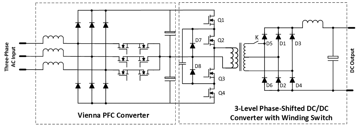
Figure 1 Charging pile using Vienna PFC and three-level phase-shift full bridge DC/DC converter
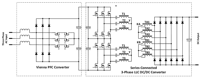
Fig. 2 Charger pile using Vienna PFC and serial three-phase LLC DC/DC converter
If a charging station has a locally isolated power transformer, the non isolated converter topology can be used. Figure 3 is a non isolated topology, which has been used in the EU 350kW ultra-high speed charging station design. Each charging pile is composed of six 60kW power converter modules completely based on SiC devices.
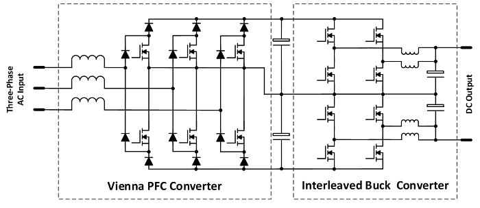
Figure 3 The non isolated charger uses Vienna PFC and a series connected Buck DC/DC converter
For isolated charger pile design, the high voltage and high frequency capabilities of SiC MOSFETs can greatly simplify topology and control difficulty. The direct benefit is to increase the power density and reduce the system cost. By using 1200V SiC MOSFETs, the output voltage of PFC can reach 600V to 900V. The downstream isolated DC/DC converter has controllable voltage doubling output and switchable transformer windings, which can work in the ideal DC transformer (DCX) mode to optimize the system efficiency. Since the DCX output is directly connected to the battery pack, its input is equivalent to a voltage source, which makes it possible to reduce or even eliminate PFC output batch capacitors. The functional modules of the new power architecture are shown in Figure 4.
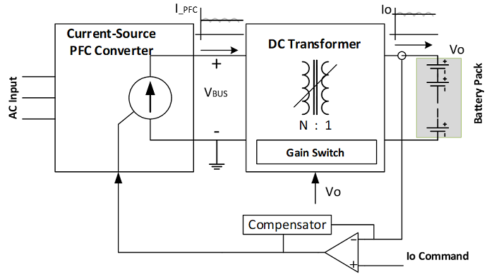
Figure 4 New AC/DC power supply structure for battery charging
Based on this power supply architecture, the topology shown in Figure 5 can be used for constant power battery charging with wide output voltage. Switch K is used to select the turn ratio of the transformer, so that the voltage multiplier can expand the output voltage range. Figure 6 shows the relationship between PFC output voltage and battery voltage.
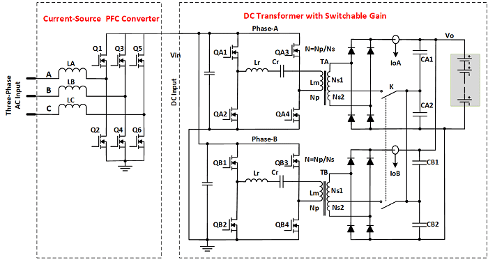
图5 高密度电源结构用于电池充电
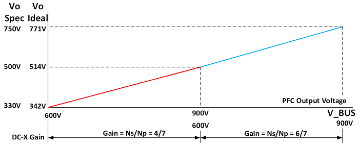
Fig. 6 DC Transformer Gain Switch
The following are photos of three-phase PFC and DCX prototypes. The circuit is still being optimized. We welcome any interested parties to join this development and turn it into a real product.

Figure 7 (a) 20Kw three-phase PFC AC/DC converter prototype

Figure 7 (b) 20Kw three-phase LLC DC/DC converter prototype
Due to the improvement of technology, the trend of low carbon emissions and the government's policy incentives, electric vehicles (EV) are a rapidly growing part of the automotive industry. According to the market and market report, it is estimated that the electric vehicle market will reach 26.9 million by 2030, with a compound annual growth rate of 21.1%. The Asia Pacific market is expected to grow fastest, followed by Europe and North America. The development of automobile industry in different countries or regions tends to different electric vehicles. Japan pays more attention to the development of hybrid electric vehicles and fuel cell electric vehicles, while other countries prefer pure electric vehicles. The most popular electric vehicles are pure battery electric vehicles (EVs), plug-in hybrid electric vehicles (PHEVs) and fuel cell electric vehicles (FCEVs). Their function blocks are shown in the figure below.
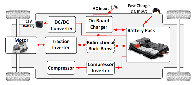
Figure 1; Block Diagram of Pure Electric Vehicle Power Supply
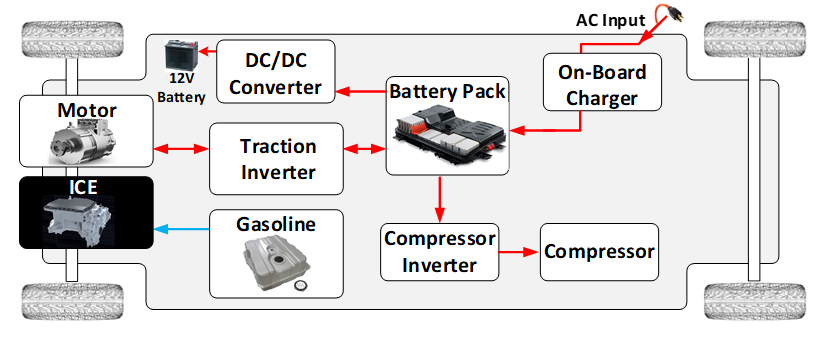
Figure 2 Power Block Diagram of Plug in Hybrid Electric Vehicle
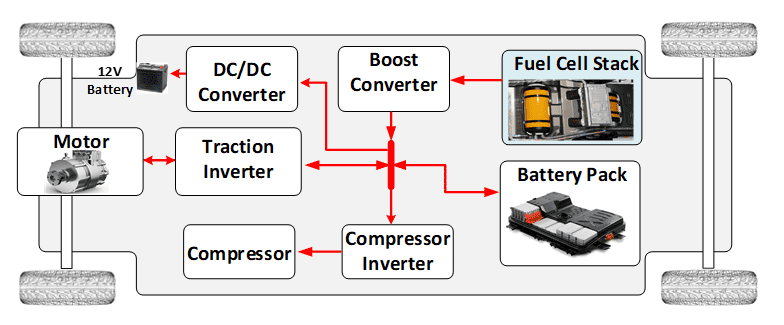
Figure 3; Power block diagram of fuel cell electric vehicle
These types of electric vehicles are developed to meet certain needs. Battery electric vehicles are very suitable for short to medium range conventional transportation. Mileage limitation, availability of charging stations and charging time are still factors that restrict their travel radius. Plug in hybrid vehicles are not limited by mileage while improving fuel efficiency and reducing carbon dioxide emissions. However, due to its dual power structure, PHEV is generally more complex in structure and high in manufacturing cost. Before the advent of low-cost high energy density batteries and the popularity of charging stations like today's gas stations, hybrid vehicles were an intermediate solution. For heavy vehicles, such as buses and trucks, fuel cell electric vehicles show the advantages of high energy density and light weight.
In order to improve the power conversion efficiency of electric vehicles and reduce the charging time, the bus voltage of new electric vehicles is being upgraded from 500V to 800V. Advanced wide band gap semiconductor SiC plays an important role in the new round of electric vehicle development& nbsp; The switching speed of SiC MOSFETs is 10 times faster than that of IGBTs, the performance will not be degraded when operating at 175 ° C junction temperature, and the switching loss will be reduced by more than 60%. In addition to improving the power conversion efficiency and reducing the physical size of the converter, SIC technology also realizes the vehicle to network (V2G) function of electric vehicles by adopting bidirectional power conversion topology. Storing unused power at night and discharging it to the grid during peak hours of power consumption will increase value for owners and help stabilize the grid.
off-board charger(OBC)
The on-board charger (OBC) is an AC/DC converter installed in the car, which can easily charge low power from the home power socket. The power range is from 3kW to more than 20kW. Due to the power limitation of household power sockets, the OBC power of ordinary electric vehicles is usually lower than 6kW. However, some high-end vehicles, such as Tesla Model-3, provide customers with three-phase power sockets with higher OBC charging power options. Commercial buses usually have larger battery capacity and require more than 10 kilowatts of charging power. The following are the topologies used in known OBC designs.
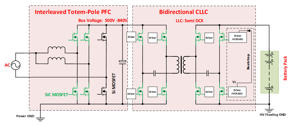
图4 双向OBC电路图(≤6kW)
The bidirectional OBC adopts staggered totem pole PFC and CLLC topology. The totem pole PFC using SiC MOSFETs is a bidirectional AC/DC and DC/AC converter, and the CLLC using SiC MOSFETs for secondary side rectification is also a bidirectional converter. The bidirectional OBC can charge the battery pack and provide the energy of the battery to the AC power grid. If bidirectional function is not required, Si MOSFETs of PFC and SiC MOSFETs of secondary side of CLLC can be replaced by diodes.
The gate driving circuit is always a problem to be considered in the design. Simple and reliable door drive is preferred. IVCR1401 is the first industrial 8-pin SiC MOSFET driver, which integrates negative bias voltage and Desat protection. It is also the only driver circuit that can use bootstrap circuit and integrate negative Bais. This feature greatly simplifies the gate level drive circuit. It is particularly suitable for LLC and phase-shift full bridge topologies where the duty cycle is always relatively stable.
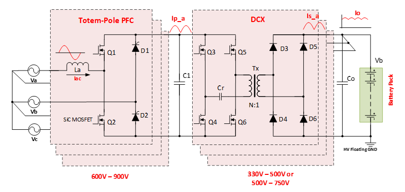
Figure 5; High power OBC with line to line and three-phase input options
DC/DC converter
All vehicles have 12V batteries (some heavy vehicles use 24V batteries). The 12V battery provides power for all entertainment equipment, chairs, windows, wiper motors, defrosting heaters, etc. Electric vehicles and hybrid vehicles have no charging generators. The 12V battery is charged by the high-voltage bus of the electric vehicle. Phase shifted full bridge and LLC topologies are commonly used in DC/DC converter design. The power rating is between 1 and 3 kW. Since the secondary side output is 12V, synchronous MOSFET rectification can achieve 99% efficiency. This makes it possible to fit the entire design into a small aluminum box without any forced cooling. For 800V bus, SiC MOSFETs are the most suitable high-frequency devices at present. It is worth noting that inside the electric vehicle, a safety relay is usually connected between the battery pack and the input capacitor bank of the traction inverter. When the vehicle is closed, the relay is open. In order to start the vehicle, before the relay is closed, the capacitor bank needs to be charged to the same voltage as the battery bank to avoid impact current. To achieve this, DC/DC converters sometimes operate in bidirectional mode.
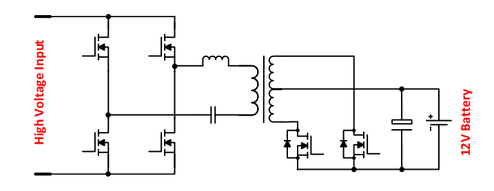
Figure 6; LLC DC/DC converter for 12V battery charging
In order to reduce cost and size, some designs combine DC/DC converters with OBC circuits, as shown in the figure below. In OBC mode, switch K connects the synchronous MOSFET rectifier circuit of high-power DC/DC output to the main transformer. In the 12V battery charging mode, the switch K connects the four synchronous MOSFETs of the rectifier circuit to the 12V battery charger circuit, and these four MOSFETs act as the main switch of the LLC to convert the power supply of the high-voltage battery pack to the 12V battery.
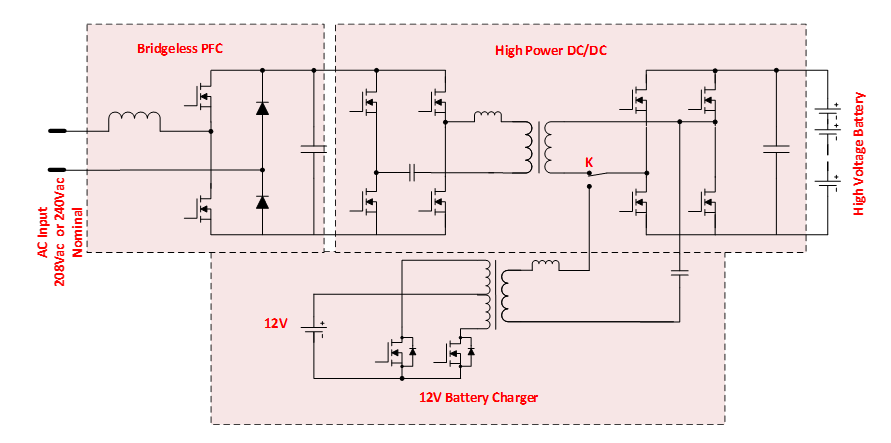
Figure 7& nbsp; OBC DC/DC combined circuit diagram
Copyright © 2024 :Husheng Technology (Shenzhen) Co., Ltd
Support:wanet